INSIDE THE REACTOR
Unlike traditional combustion or gasification, the GFS Gasification System does not incinerate or rely on thermal energy alone to break down the feed material. The process can be described as multiple reactions occurring simultaneously or a controlled chain reaction where electric, thermal, chemical, photo, and free radical reactions are taking place and interacting with one another. The reactions inside the vessel can be simplified into three zones for explanation purposes:
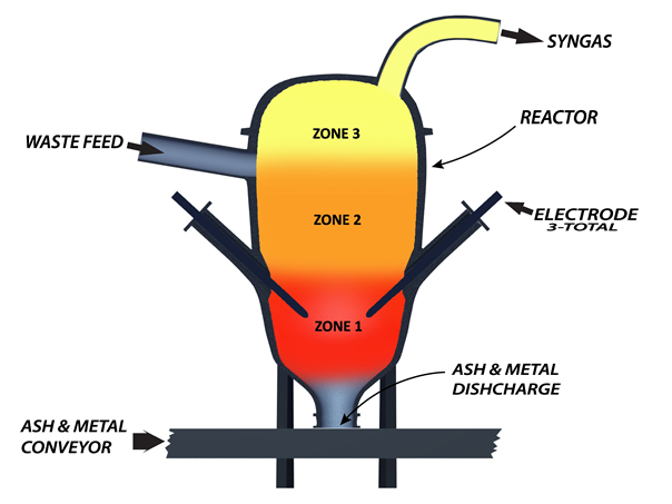
Zone 1 : As detailed in the following paragraphs, a series of reactions occur simultaneously in Zone 1. In addition to the conversion from waste to syngas which takes place in Zone 1, two other processes are also occurring – 1) the vitrification of inert elemental material such as calcium, phosphorus, etc. which doesn’t exist in a gaseous form, and 2) the immediate cooling of any metals in the feed material.
Electrochemical Reaction : High amperage electricity is delivered to the center of the gasification chamber via precisely placed electrodes. The high electrical energy alone would be enough energy to break down most material over time but, in this application, the electric arc serves primarily as a catalyst and energy source sustaining the multi-stage reaction occurring inside the vessel. Alone, the electric arc will still function as a powerful redox agent to transfer electrons between molecules and break down incoming feed material.
Thermochemical Reaction : The temperature in the region near the electric arc typically ranges between about 12,000°C to 15,000°C depending on the intensity of the electric current powering the electrodes. At this temperature, the chemical bonds of compounds are broken and what was previously water, wood, a piece of rubber tire, etc. transitions back to singular molecules in their elemental form.
Chemical Reaction : Simply put, a chemical reaction is the process that leads to the transformation of one set of chemical substances to another set of chemical substances. A simple and relevant example is the transformation from water and carbon molecules to syngas 3H2O + 3C H2 + CO + CO2 + CH4. This transformation, or chemical reaction, occurs millions of times per second and is achieved through the application of energy in the right environment. Energy is consumed or released with each molecular bond and cleavage until equilibrium is achieved and the stabilized syngas exits the gasification chamber.
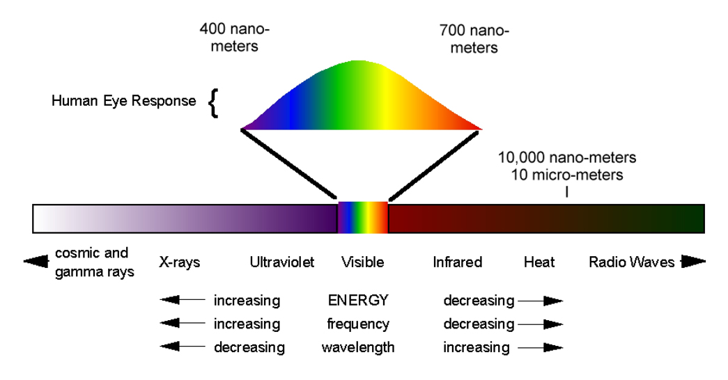
Photochemical Reaction : Photochemistry relates to the chemical effects of light on organic matter. As the electric arc strikes between the electrodes and the surface of a water table maintained a short distance beneath the electrodes, electrochemical and photochemical reactions begin to occur. The intense series of reactions emits a spectrum of light between ultraviolet and infrared. As H2O steam passes through the electric arc, it is ionized and, also serving as a stabilizer gas, helps to form a suspended field of plasma, or dissociated H-O free radicals, which yields a new atmosphere or environment wherein reactions can occur which would not be possible under normal circumstances. This area releases electromagnetic radiation on a fairly wide spectrum, from infrared to ultraviolet, with a greater distribution towards ultraviolet. The energy required to dissociate the chemical bond H-O amounts to 431,000 Joule/mole. By dividing Planck’s constant (6.62 x 10⁻²⁷ erg s) by the Avogadro’s number, then the frequency is 1.0806 x 10¹⁵ Hz which is in the frequency is in the ultraviolet area. Ultraviolet ranges from 40 to 4,000 Angstrom and has a wave length of around 280 Angstrom (28 nm). The temperature range of 12,000°C to 15,000°C achieved near the arc zone, which is indicative to the amount of energy inside this zone, cannot be achieved solely by the intensity of the electricity (250 kW to 350 kW per ton of feedstock with a 55% moisture content) used to initiate the reaction. This high temperature is attributable to the energy produced by the free radicals and the multiple reactions which follow the H-O dissociation as the free radicals not only react with the carbonaceous feed material but also with themselves. Note: The Warm Ionized Medium (WIM) which makes up roughly 20% to 50% of the Interstellar Medium (ISM) of the Milky Way is comprised primarily of ionized hydrogen molecules residing at a temperature of around 7,727o C, not too dissimilar of the conditions inside GFS’s gasification chamber.
Free Radical Reaction : The homolysis process (chemical bond dissociation of a neutral molecule generating two free radicals) is demonstrated in the below chemical equation where h is Planck’s constant and v is frequency.
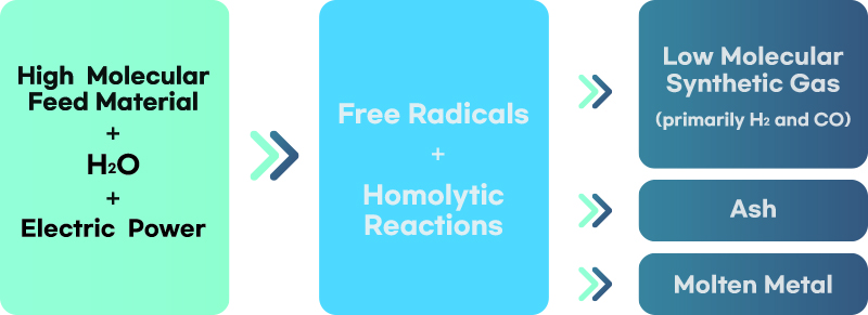
Millions of single hydrogen atoms inside the gasification chamber work as a potent reducing agent while the hydroxyl radical works as a powerful antioxidant. The free-radical products of the water hemolytic reaction above attack the carbonaceous material, breaking it down to its individual molecular components, thus releasing further free radicals and generating a chain reaction. Standard electric arc gasification is dependent upon thermal energy alone, whereas GFS utilizes this controlled chain reaction of the free radicals to break the chemical bonds in the feedstock at the molecular level. The hydrogen and oxygen molecules required for this reaction come from the moisture in the feedstock, the waterbed inside the reactor and any additional H2O mixed with the material or added directly into the reactor vessel as needed. Once initiated, the controlled free-radical chain reaction proceeds without the need for additional energy input so long as the conditions are sustained. The benefits of the energy released and the reducing properties of the millions of highly excited singular hydrogen molecules during the continuous free-radical chain reaction which utilizes the H and O molecules pulled from the moisture in the feed material is greater than any inefficiency one would assume to be present when processing wet feed material. This is another key differentiator as the energy required to break these molecular bonds and process water under any other condition, such as that in an arc furnace or under a plasma torch, may be achievable but would certainly be cost prohibitive and non-sustainable in any business model due to the costs attributable to the required energy input.
The net result of these free-radical reactions, as illustrated below, is the conversion of the relatively high molecular weight carbonaceous feed material into low molecular weight gaseous products, primarily hydrogen and carbon monoxide, but occasionally carbon dioxide, methane or other higher carbon gasses, resulting in the complete decomposition of the cellulosic molecules.
Radical recombination provides a control mechanism within the process as it leads to a net reduction of the number of radicals, thus preventing an uncontrollable continuation of the chain reaction.
The overall process can be therefore divided into three stages : 1) initiation, in which the number of radicals is increasing as the light and electrochemical energy provided by the arc cause chemical bonds in the water and the feed material to break, producing radicals which react with other feed molecules to form still more radicals and cause the breakage of more chemical bonds 2) propagation, in which, due to the constraints of the amount of feed material, water and electricity, an equilibrium of sorts is achieved and the number of radicals remains essentially the same although the nature of the radicals may change and 3) termination, in which the number of radicals decreases as the level of excitement decreases, and the radicals form bonds with one another and with the carbonaceous waste material.
Both the hydroxylic radical, which behaves like a potent oxidant, and the isolated hydrogen atom have a very aggressive attitude toward the bonds of the organic molecules and tend to generate a chain reaction, thus promoting the formation of lighter or elementary molecules. While many of the individual steps occurring in the process involve oxidations or reductions, overall, the result cannot be considered an oxidation or “redox” process of the feed material since no oxidant is ever consumed. Similar reactions occur in pyrolysis – however, pyrolysis is most often associated with oxidation by atmospheric oxygen or some other redox agent and is almost always associated with some type of net oxidation or reduction of the fuel source. The reactions taking place inside the reactor are less akin to those of pyrolysis and are better described as cracking reactions that result in the reorganization of the molecular structure of the fuel material without any loss to the energy as a fuel source contained therein.
Zone 2 : This area, directly above Zone 1, is where feed material enters the reactor and where the propagation phase of the free-radical reaction takes place. The carbonaceous material is exposed to a flood of extremely reactive free radicals created in Zone 1. Zone 2 is characterized by high thermo-chemical and photo-chemical activity. Extreme heat combined with the extremely reactive free radicals coming from Zone 1 initiates pyrolysis and the beginning stage of decomposition of the carbonaceous feed material as it falls at the speed of gravity into Zone 1. Tars and chemical compounds begin to break down and H2O inside and outside of the material begins to convert to steam. This steam reacts vigorously with the carbonaceous waste and eliminates potential soot formations. This is explained further in Appendix A.
Zone 3 : The product in Zone 3 consists of steam and a medium BTU syngas. The syngas produced in Zone 1 cools some as it passes upward through the feed material entering the reactor and exchanges heat. The syngas exits the reactor at about 1,200°F (649°C) but has been recorded as high as 1,472°F (800°C). The pressure is slightly more than atmospheric pressure – just enough to stop any inflow of air through the seals or portals.
SYNGAS COMPOSITION
As previously stated, the gas produced by the system is released from the upper part of the reactor vessel at approximately 1,200°F (649°C). The gasification process itself is done with zero air emissions. The end use of the syngas will determine the pathway it takes from this point forward and how much cleaning is needed. The syngas consists of carbon, hydrogen and oxygen gasses in various molecular structures. Depending upon the feedstock, there may also be very small traces of dust and acid gasses such as HCl, H2S, and SO2 that can be easily treated and removed. Typical syngas composition is shown in chart on p. 8. Syngas quality and consistency are important factors in the GFS gasification process. Syngas composition and BTU level can be manipulated to achieve preferred parameters. Feed material with a higher moisture content will result in a larger volume of syngas with a lower BTU. Drier feed material will result in less syngas with a higher BTU. Nonetheless, the volume and BTU output is both predictable and manageable.
| GAS | PERCENT RANGE |
|---|---|
| H2 | 50% to 60% |
| CO | 30% to 40% |
| CO2 | 5% to 10% |
| CH4 | 1% to 5% |
| CnHm | 1% to 2% |
| H2O | < 0.1% |
| Other | < 0.1% |
Commercial Applications
-
WASTE TREATMENT AND DISPOSAL
The Naples facility was designed as a method for disposing waste. Material such as autofluff, biosludge, plastics, rubber tires and more were safely broken down and eliminated as an alternative to landfilling. The high temperatures of 12,000°C to 15,000°C in the arc zone of the reactor vessel safely break down harmful chemical compounds making the GFS process a reliable solution for disposing of residential, commercial and industrial waste streams or treating sewage effluents, contaminated soil, medical waste, and even residuals from other waste-processing facilities.
-
COMBINED HEAT AND POWER (CHP)
Because the syngas leaves the reactor at about 1,200°F (649°C), valuable heat can be captured and used in downstream processes. There are no gaseous emissions during the conversion from solid waste to useable syngas. The only gaseous emission comes downstream if the syngas is burned. Then the emission is very similar to the CO2 emitted from any other commercial operation. The combination of C, H, and O gasses in this process result in a medium BTU syngas, varying from about 300 BTU to about 700 BTU, which can be used in a variety of ways. Typical uses include producing plant steam for operating wood drying kilns or heating buildings, high pressure steam production for operating turbines, and product gas for operating combustion turbines or gas burning boilers. Numerous pathways and scenarios have been engineered to capture the available energy while adapting to existing equipment.